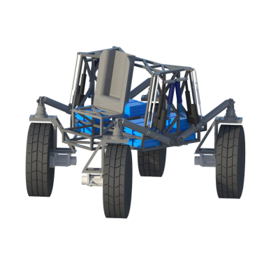
Vehicle for Extraterrestrial Research, Transportation, and Exploration

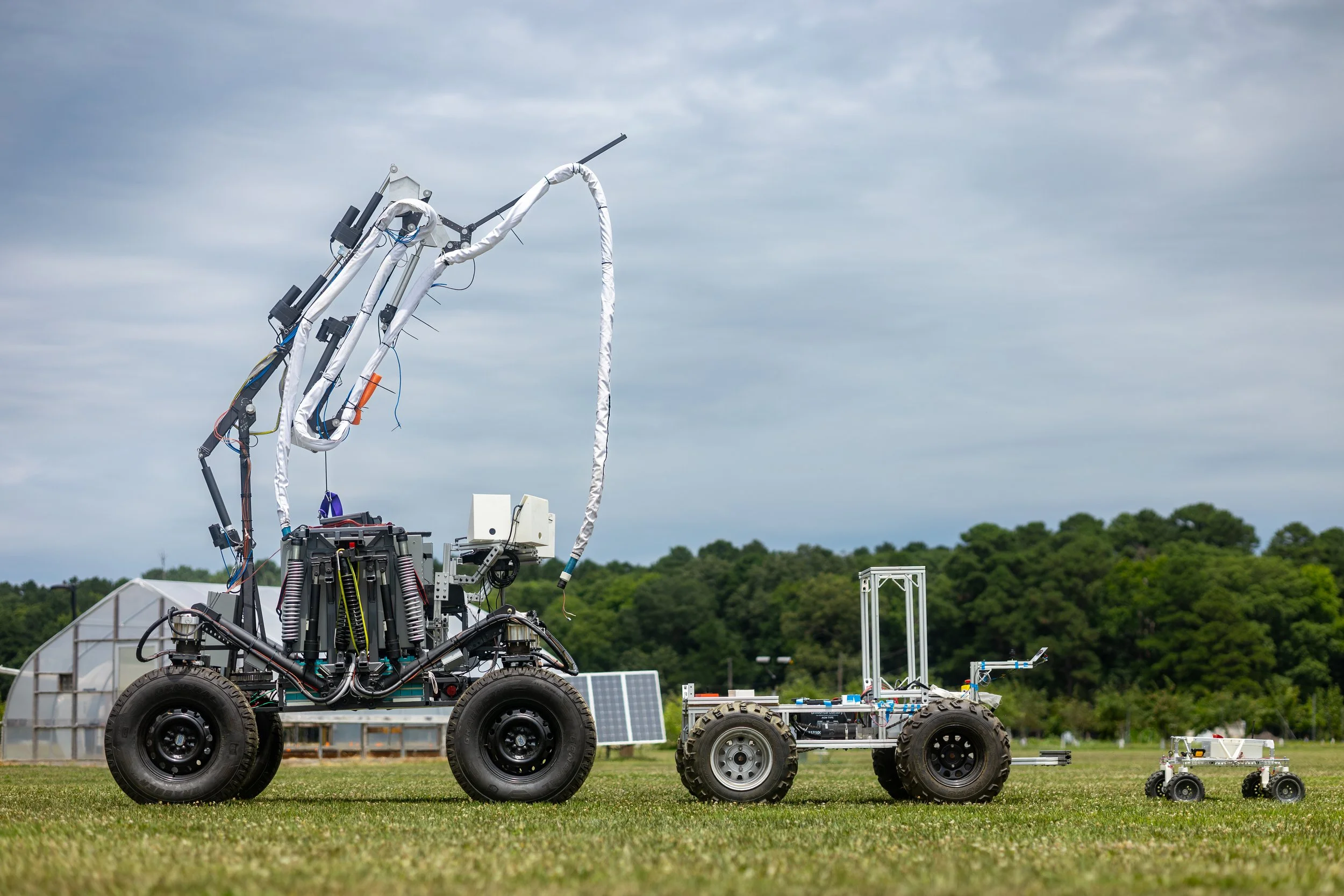
VERTEX is the SSL’s latest and most advanced roving vehicle aiming to ease the exploration burden of Extravehicular Activities (EVAs) on the lunar and Martian surfaces. Specifically, VERTEX is the highly-capable mobility chassis that supports the BioBot concept which combines this rover with a 5-meter umbilical tending planar manipulator and a lightweight, highly mobile spacesuit simulator.

Please note - this page focuses on the development of the VERTEX roving vehicle (and is very picture heavy - I recommend reading on a computer screen).

If you’re interested in seeing the vehicle during testing, please see the BioBot page where the rover is integrated with the other subsystems for field trials!

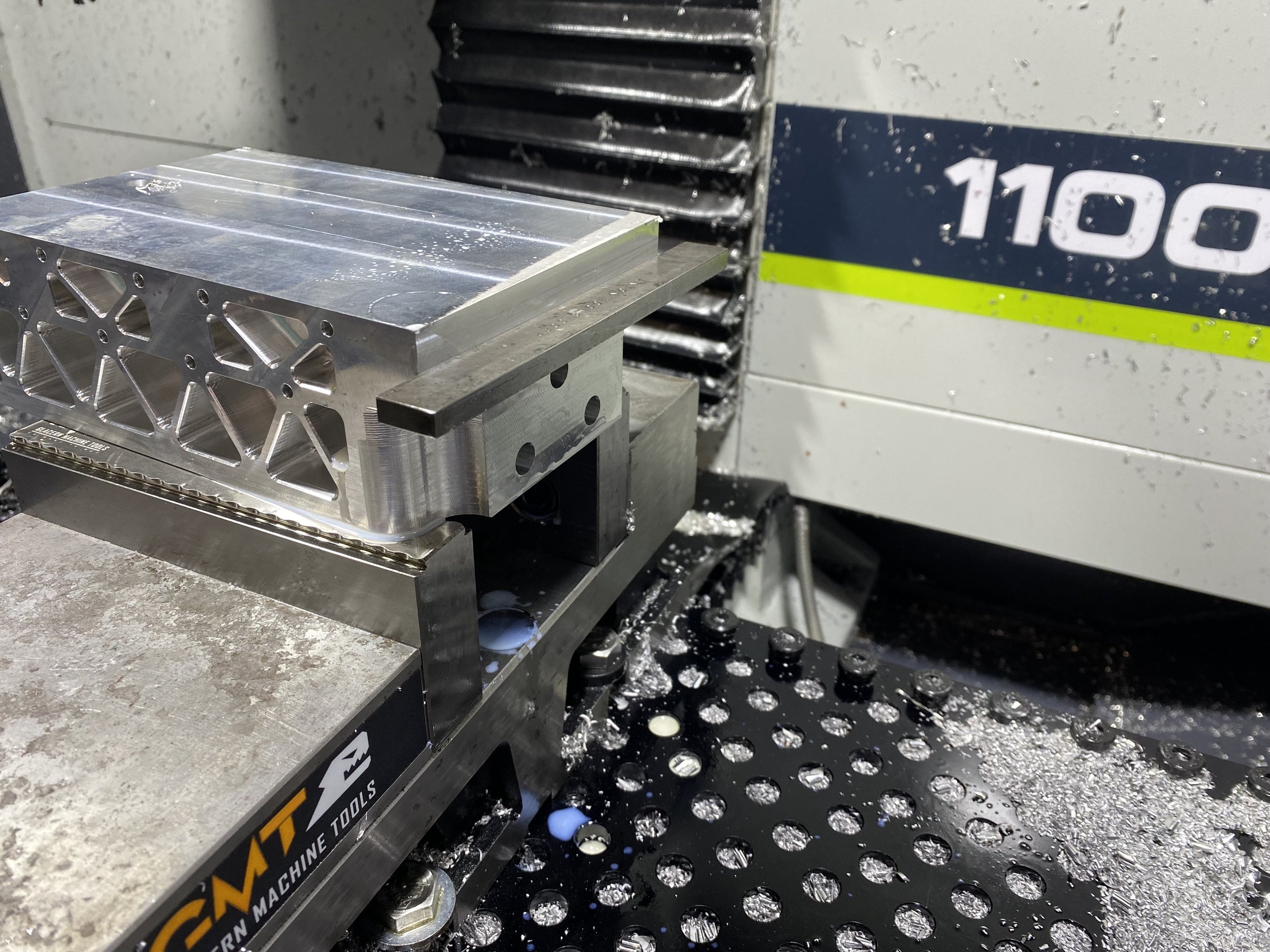
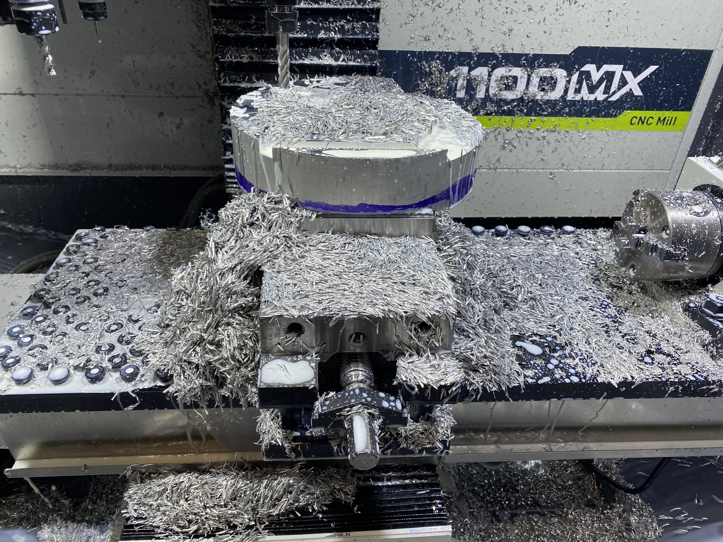
I am the co-hardware designer for VERTEX, working alongside Nicolas Bolatto for nearly four years in the creation of this vehicle. I am also the project’s head fabricator and lead the manufacturing of the rover (and arm!), a vast majority of which was completed in-house.

So, what did we make?

VERTEX is an Earth analogue lunar roving vehicle designed to facilitate testing of an array of concepts of EVA operations in Earth conditions. The design started with a lunar systems design for a single-astronaut vehicle during an ENAE788X graduate course alongside three other team designs, of which the best features were combined to create a high-level lunar systems design featuring heritage design elements such as brushless DC motor & Harmonic Drives combined with forward-thinking design elements like active articulation of the rover chassis for additional stability including passive spring damping.

This design was then translated by Nicolas Bolatto and myself to a capability-matched Earth design under the guidance, funding, and design reviews of a NASA Innovative Advanced Concepts (NIAC) contract alongside a rover-focused eXploration Habitat (X-Hab) project. This Earth rover is named VERTEX, and is focused on maintaining exploratory capabilities such as slope climbing, speed, and payload capacity under the burdening conditions of Earth gravity. The design does not maintain lunar-required systems such as advanced dust sealing, deployment mechanisms, and others.

Nicolas Bolatto and I in front of BioBot
  • Vehicle Mass: 2,600 lbs (~1180 kg) - including umbilical tending manipulator

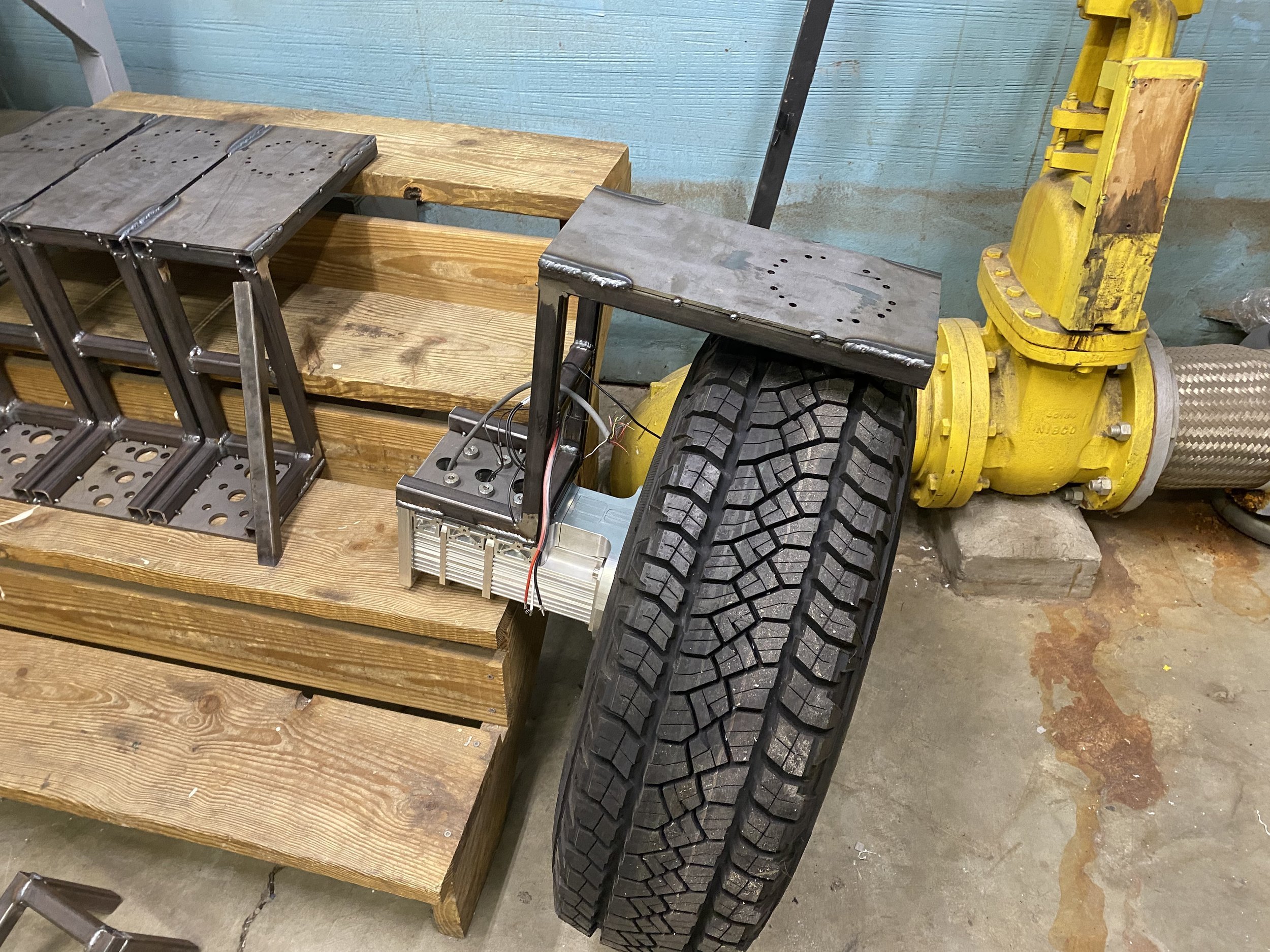
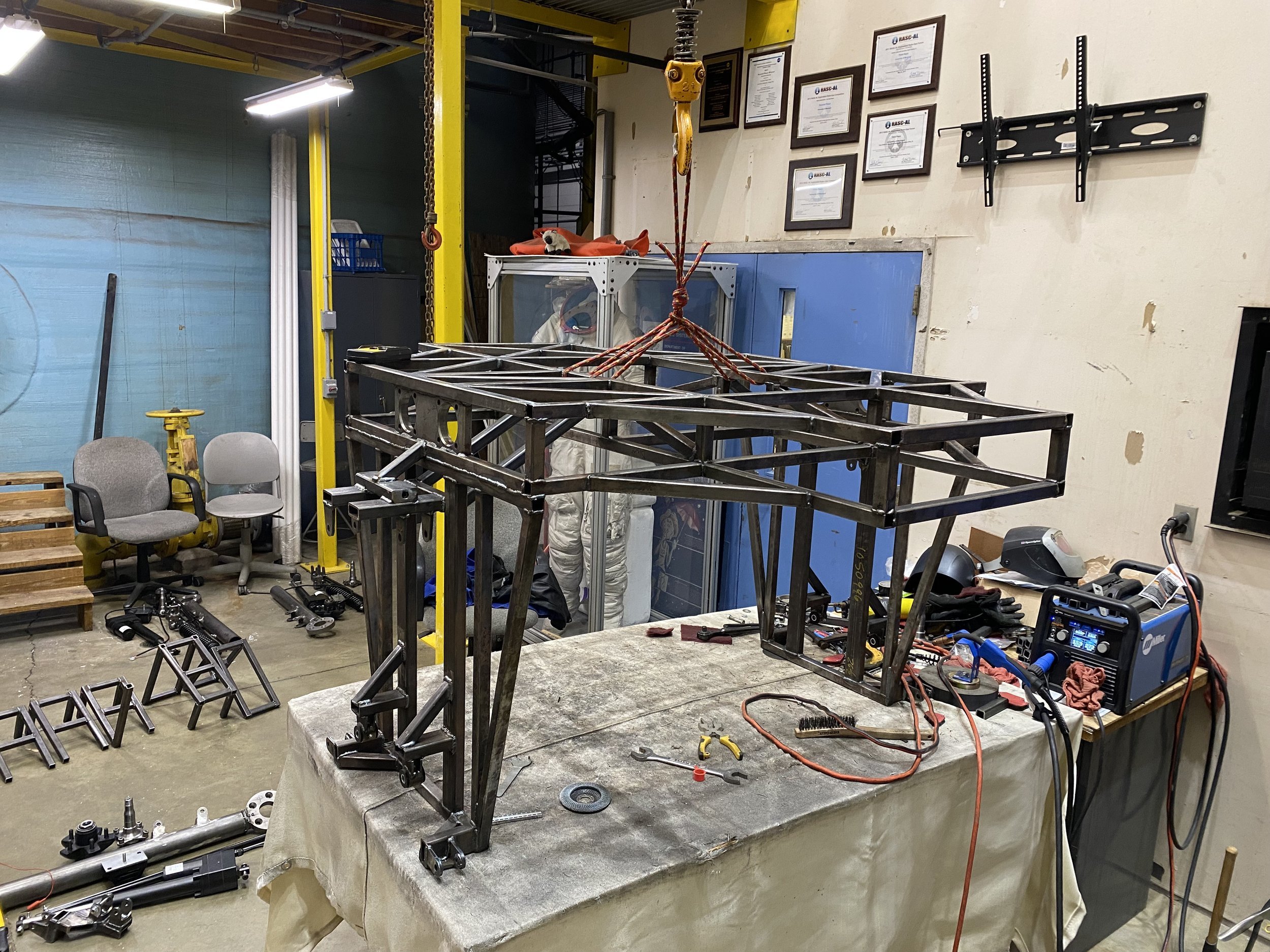
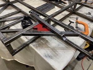
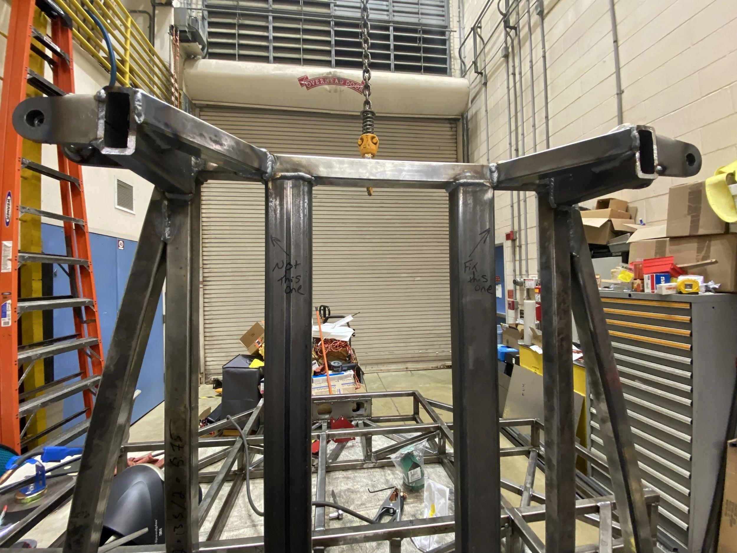
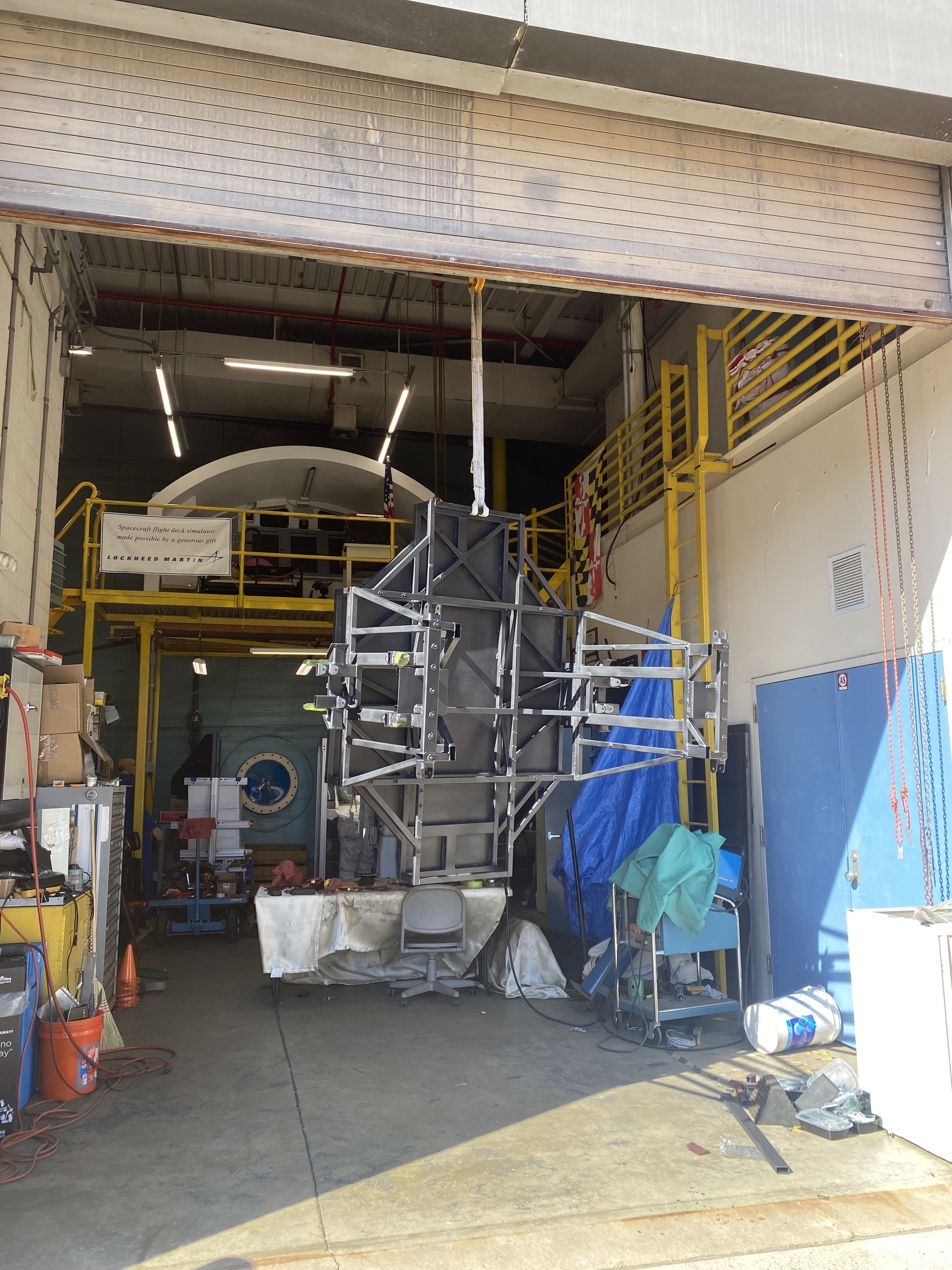
  • Chassis and main structures are square mild steel MIG welded for rapid development and low-bar for students

  • Payload capacity ~1,000 lbs, greater payloads possible dependent on suspension configuration

  • Top Speed: >20 mph (tested to ~15 mph as of now) - 4.5 m/s Sustained up slopes

  • Slope climbing ability: 30° (Terramechanics/soil dependent)

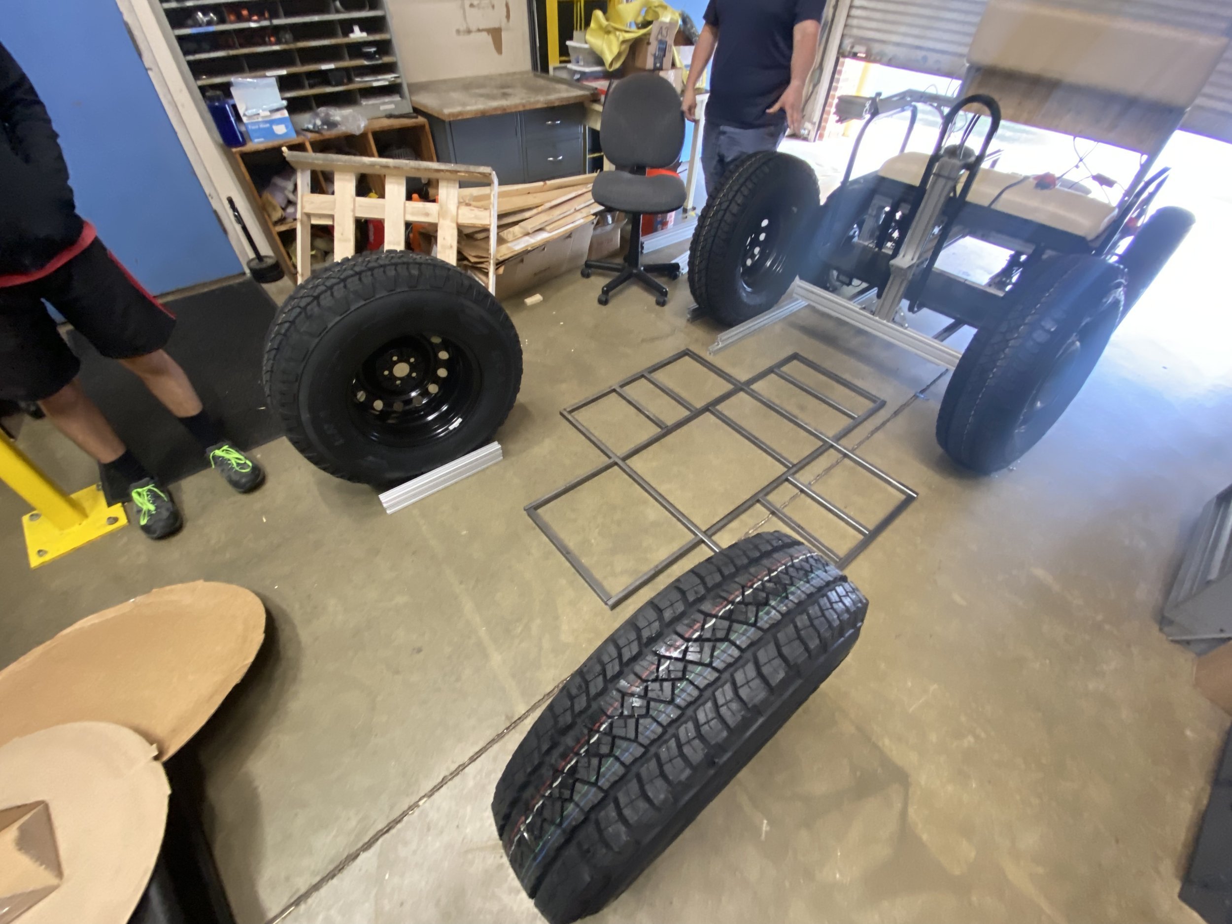
    • 32” Commercial Tires

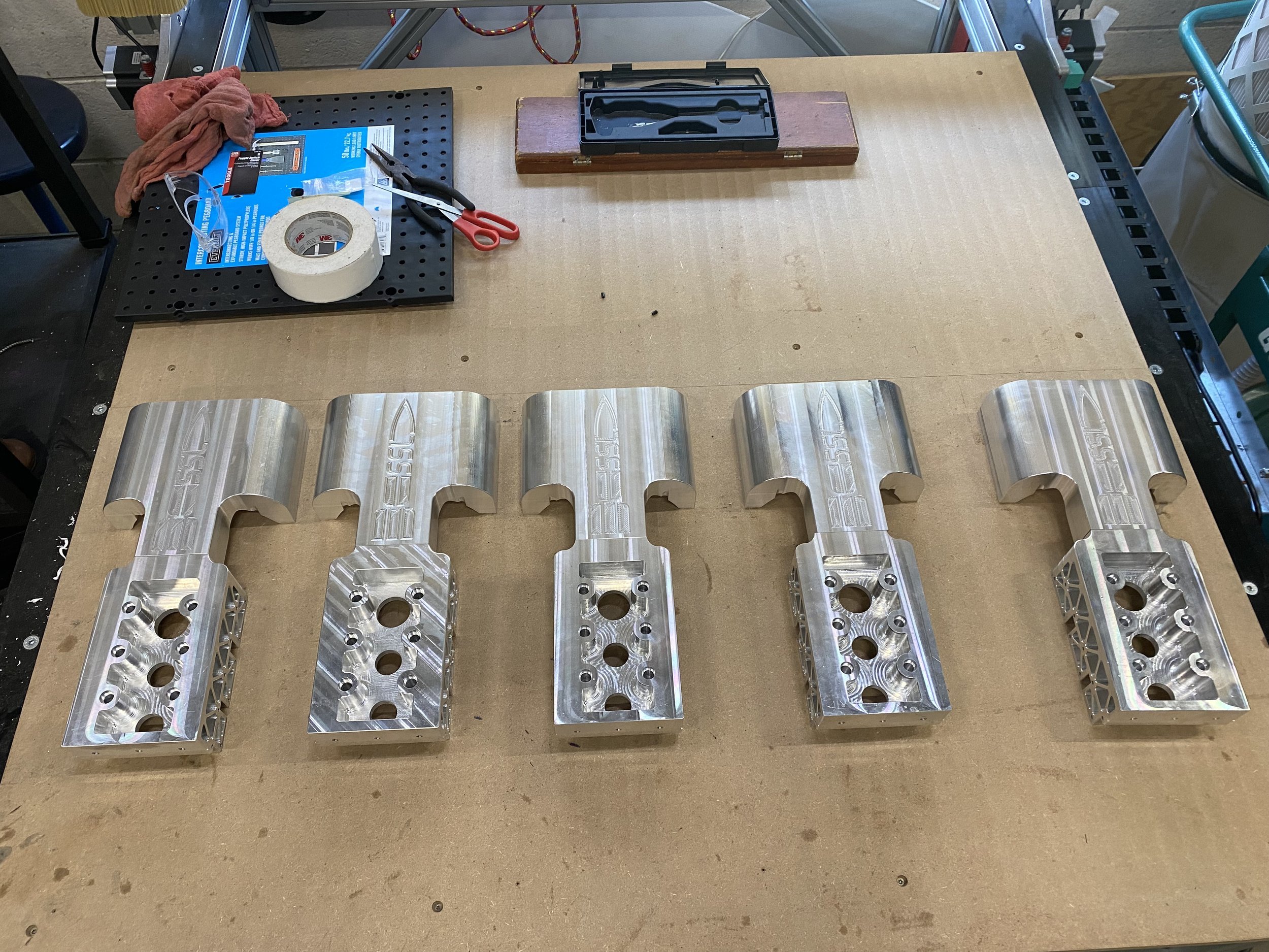
    • Brushless DC motor with 33:1 planetary gearset

    • 2,400 ft-lbs continuous vehicle torque / theoretical 4,000 ft-lbs peak

  • Chassis leveling capability: Pitch 28.5°, Roll 40°

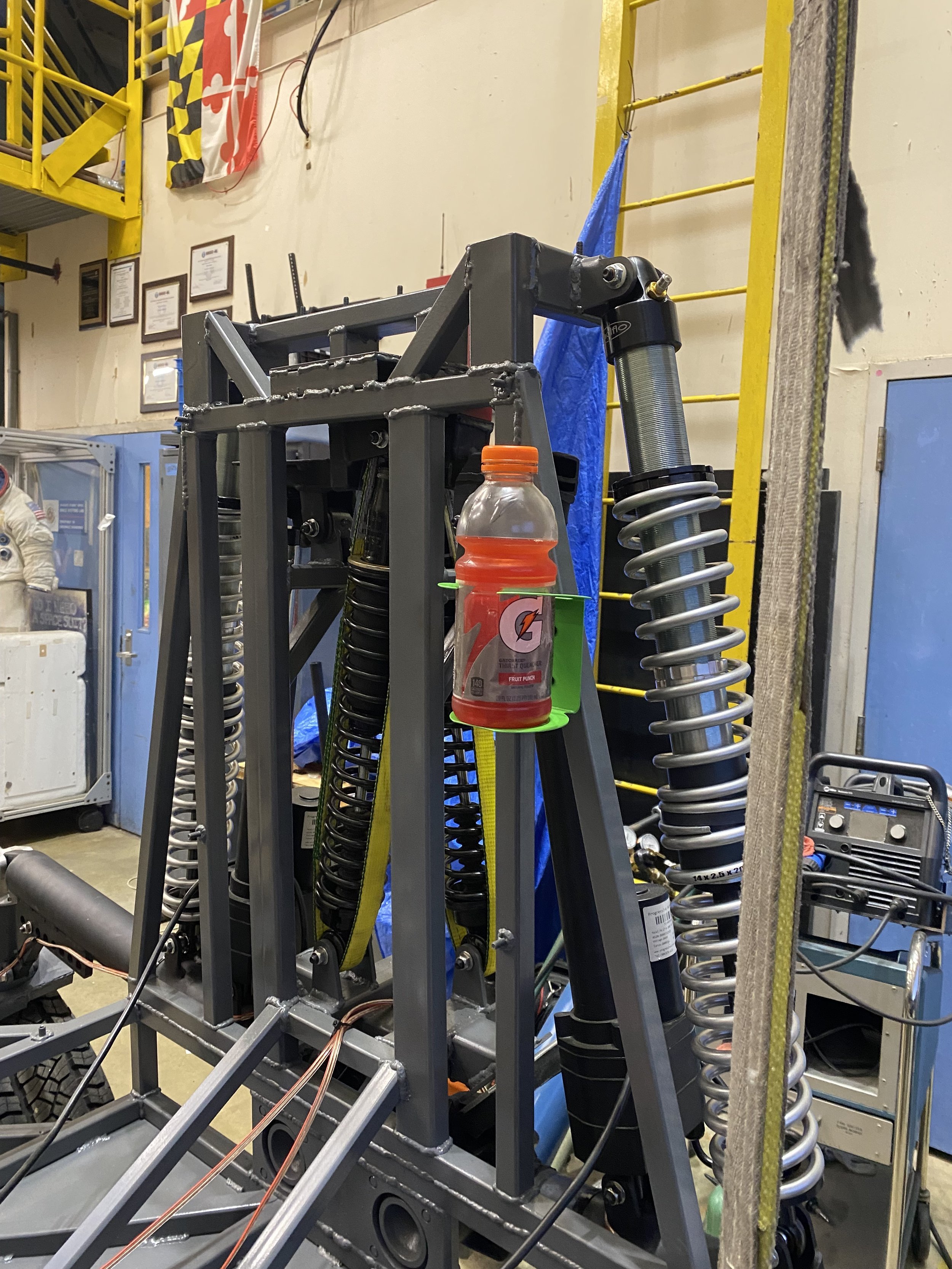
    • 24V electric linear actuator driven, with coilover suspension offloading

    • Spring-damper integration for suspension via. series elastic actuator integration

    • Chassis able to raise over 50” high and lay flat on ground

  • Four wheel independent steering

    • Brushless DC motor and 100:1 Harmonic Drive actuator

    • Incremental and Absolute Encoders

    • +-180° steering control

  • 96V DC, 300A continuous, LiFeMnPO4 batteries

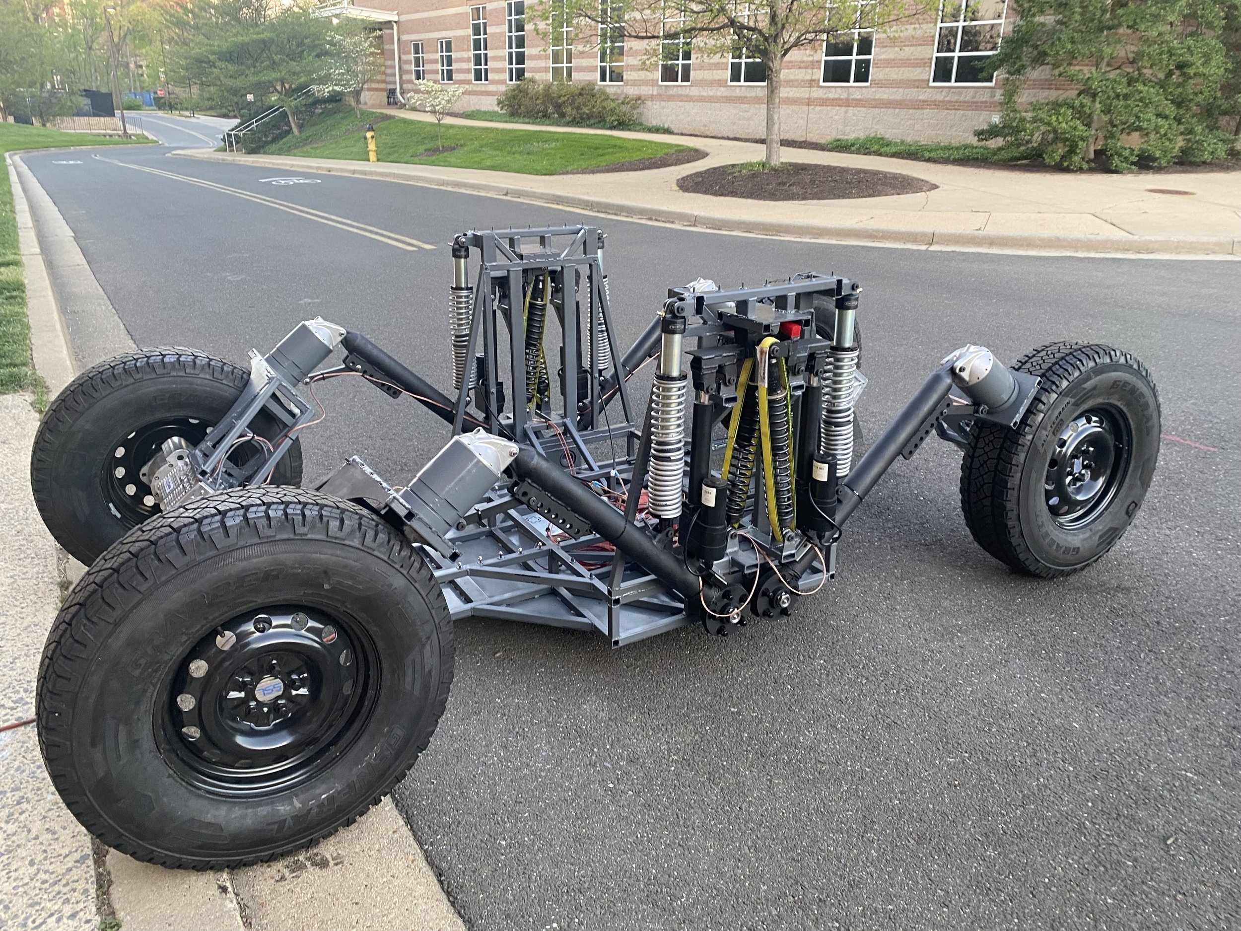
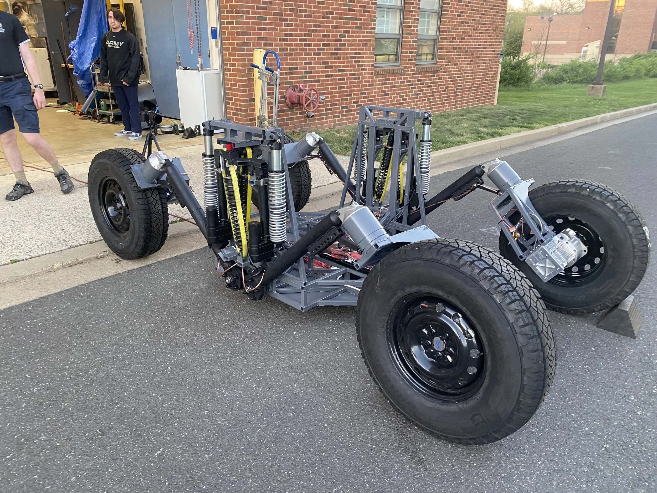
Reversing down gravel path with two unsuited operators!

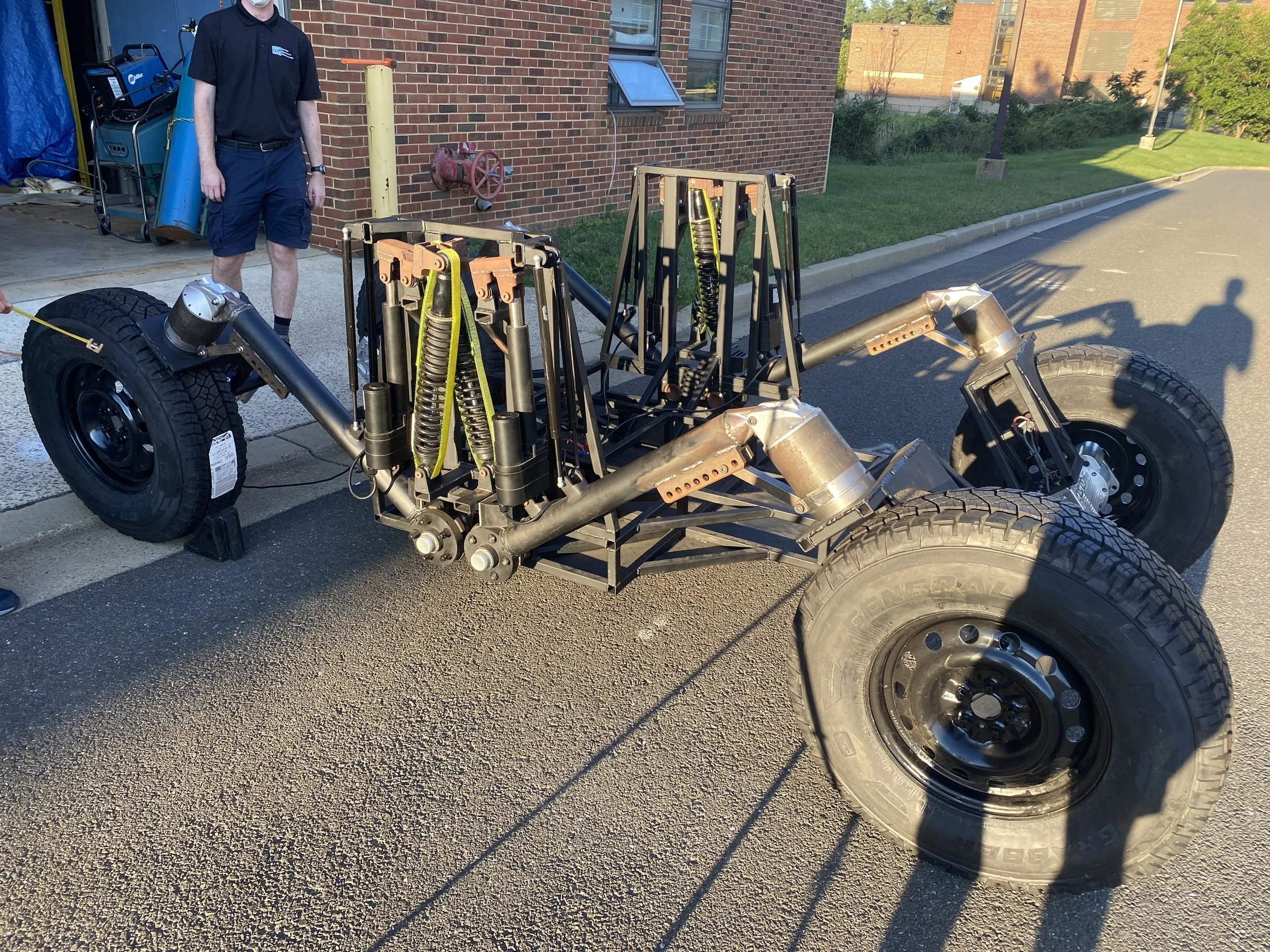
Easily transportable via automotive trailer!

Side profile during first field trial

Technical Specs:

The Technical Goods

Lunar systems design: This figure features the final four high-level systems designs of a lunar mobility system from ENAE788X. Our team was the bottom-right figure featuring most notably the high-range independently articulated suspension system that eventually made it into the VERTEX design, but varying aspects of the other designs Nic and I also included in the final design.

Earth Design Step 1: The first rover design was a major effort in the initial component placement and rapid iteration of structures to meet evolving demands from rapidly changing suspension, steering, and traction systems. Volumetric estimations for tools, electronics, and human needs were being narrowed down, and component placement was beginning finalization. Commercial pneumatic tires were sourced to match our desired terramechanics values. We also did some renders using the vehicle as a mobile artificial gravity offloading system for continued Earth-based testing of EVA as an alternate use case.

Earth Design Step 2: The second full iteration of the vehicle saw significant improvement to the system as a whole, trending towards more viable designs across the board. Steel structures had been improved for both strength and to accommodate more true estimations of electronics and tool volumes. The first manufacturable suspension design was taking shape, including the use of gas springs to offset the heavy increase in rover mass and allow for the desired articulation ranges.

Earth Design Step 3: The next evolution was an incremental step focusing on manufacturability and pushing more subsystem designs to finalization. Subsystems marked as complete and beginning production in this stage included the original suspension design (later updated - more on that further down), updated steering designs, new caster/camber adjustment designs, finalized over-wheel steering arches, finalized traction motor/gearbox support structure, and a finalized chassis. Certain areas of the design such as the chassis was created for maximum flexibility for adjustments to items not finalized such as the umbilical arm mounting, human interface structures (seats/control panels to be iteratively upgraded), and electronics boxes.

The Built Design: At this point, the rover was ready to begin fabrication! Tweaks would be made as we made our way through the manufacturing process. I focused most of my efforts on the welding of the main structures (chassis, swingarms, and over wheel steering arches) and milling all the aluminum support structure for the traction motors/wheels. Please find a gallery below with a large collection of images through the build process!

Suspension Upgrade: The old suspension design had an issue with mechanical advantage as the swingarms moved through their articulation range - this suspension redesign is detailed heavily in our ASCEND 2023 paper with lots of detail on the two systems, but in essence my analysis showed that as the swingarms move further into either extrema of the articulation range I needed to provide more and more force to maintain stability. The old system could statically support the rover in any orientation, but as soon as a dynamic load was seen such as a person jumping or running over a rock the suspension would bottom out and not rebound. This issue has been fixed with the new 14” stroke (32” total length) coilovers and includes a customizable preload to allow the ride quality to remain the same across changes in large payloads on the vehicle. Please see these photos of the vehicle undergoing this upgrade path!

As Built Vehicle: Once the rover had most of the mechanical assembly completed, a phase of electronics integration and checkouts occurred. Over the course of this time the vehicle gained extra

Next
Next

BioBot